Beverage antenna
This article needs additional citations for verification. (October 2015) |
_(14569732060).jpg)
The Beverage antenna, a very early type of wave antenna or traveling wave antenna, is a long-wire receiving antenna mainly used in the low frequency and medium frequency radio bands, invented by H.H. Beverage in 1921.[1] It is used by amateur radio operators, shortwave listeners, longwave radio DXers, and for military applications.
A Beverage antenna consists of a horizontal wire from one-half to several wavelengths long (tens to hundreds of meters / yards for shortwaves; up to several kilometres / miles for longwaves) suspended above the ground, with the feedline to the receiver attached to one end, and the other end of the wire terminated through a resistor to ground.[2][3] The antenna has a unidirectional radiation pattern with the main lobe of the pattern at a shallow angle into the sky off the resistor-terminated end, making it ideal for reception of long distance skywave (skip) transmissions from stations over the horizon which reflect off the ionosphere. However the antenna must be built so the wire points in the direction of the transmitter(s) to be received.[4]
The advantages of Beverage antennas are their excellent directivity, wider bandwidth than conventional resonant antennas, and the ability to clearly receive distant and overseas transmitters. Their disadvantages are very long physical size, requiring considerable land area, and because of the length, being unfeasible to rotate to different reception directions. As a work-around, antenna installations often use multiple Beverage antennas to provide wide azimuth coverage.[4]
History
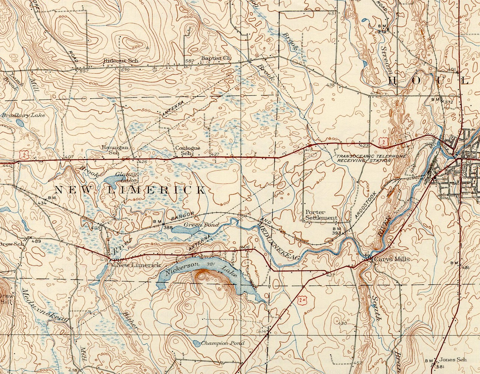
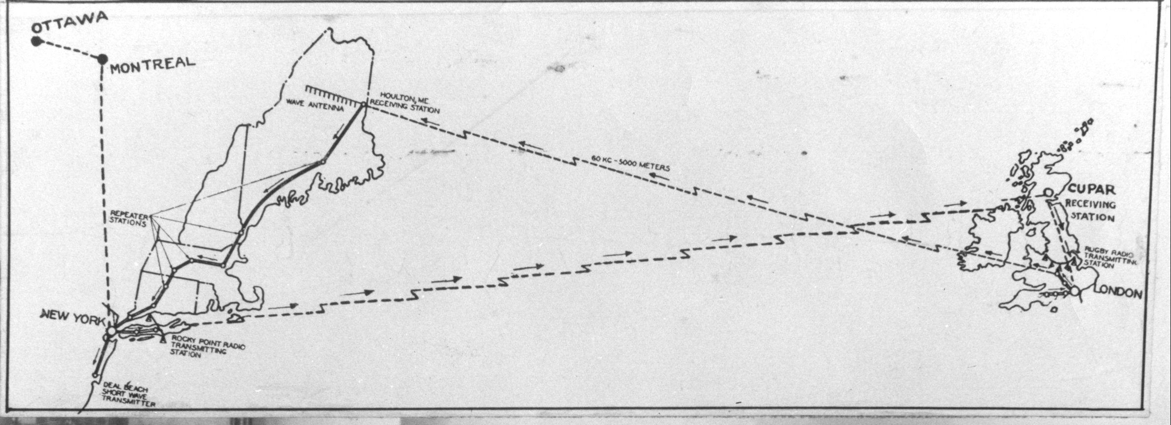
[edit]Harold Beverage experimented with receiving antennas similar to the Beverage antenna in 1919 at the Otter Cliffs Radio Station.[5][6] He discovered in 1920 that an otherwise nearly bidirectional long-wire antenna becomes unidirectional by placing it close to the lossy earth and by terminating one end of the wire with a resistor. In 1921, Beverage was granted a patent for his antenna. That year, Beverage long-wave receiving antennas up to 14 km (9 miles) long had been installed at RCA's Riverhead, New York,[7] Belfast, Maine,[8] Belmar, New Jersey,[9] and Chatham, Massachusetts [10] receiver stations for transatlantic radiotelegraph traffic. Perhaps the largest Beverage antenna – an array of four phased Beverages[11] 5 km (3 miles) long and 3 km (2 miles) wide – was built by AT&T in Houlton, Maine, for the first transatlantic telephone system,[12] opened in 1927.
Description
[edit]
.gif)
The Beverage antenna consists of a horizontal wire one-half to several wavelengths long, suspended close to the ground, usually 3 to 6 m (10 to 20 feet) high, pointed in the direction of the signal source.[3][2] At the end toward the signal source, which the induced signal travels away from, the wire is shorted to ground through a resistor whose electrical resistance is close to the value of the characteristic impedance of the antenna wire (modeled as a transmission line), which is typically 400~800 Ohms. At the end that the arriving waves travel towards, the antenna is connected to the receiver through a transformer ("balun") to the receiver's feed line. The tranformer matches the antenna's 400~800 Ohm impedance to the line's impedance, conventionally either 50 or 75 Ohms.[4]
Operation
[edit]Unlike other wire antennas such as dipole or monopole antennas which are typically used on their resonant frequencies, with the radio currents traveling in both directions along the element, bouncing back and forth between the ends as standing waves,[13] the Beverage antenna is a traveling wave antenna; the radio frequency current travels in one direction along the wire, in the same direction as the radio waves.[3][2][14](pp 300–310) The lack of resonance gives it a wider bandwidth than resonant antennas. It receives vertically polarized radio waves, but unlike other vertically polarized antennas it is suspended horizontally and close to the ground, and requires some resistance in the ground to work.
The Beverage antenna relies on "wave tilt" for its operation.[15] At low and medium frequencies, a vertically polarized radio frequency electromagnetic wave traveling close to the surface of the earth with finite ground conductivity sustains losses that are greater nearer the ground; the reduction near the ground causes the net wavefront to "tilt over" at a small angle.[3][2][14][4] Where this happens, the electric field is no longer perpendicular to the ground, but inclined at an angle. Because of its inclination, the radio wave has a small component to its electric field parallel to the Earth's surface. The horizontal wire of the Beverage is suspended close to the Earth, and approximately parallel to the wave's direction, and the small horizontal electric field generates a horizontal wave of RF electrical current in the wire, propagating in the same direction as the external radio waves. The RF electrical current traveling along the wire add in phase and amplitude throughout the length of the wire, cumulatively producing the maximum signal strength where the current reaches the far end of the antenna, where the antenna wire connects to the matching transformer that smoothly feeds (no retro-reflection) the electrical current into the line to the receiver.[4]
The antenna wire and the ground under it together can be thought of as a "leaky" transmission line which absorbs energy from the radio waves.[14] The velocity of the electrical waves in the antenna wire is less than the speed of light through the air, due in part to capacitance between the wire and the nearby ground. The velocity of the wavefront along the wire is also less than the speed of light due to its angle. At a certain angle, θmax, the two velocities are equal. At this angle the gain of the antenna is maximum, so the radiation pattern has a main lobe at this angle. The angle of the main lobe is given by[14](p 310, eq. 8.18)

where
- is the length of the antenna wire,
- is the receiving wavelength.


The antenna has a one-directional reception pattern, because RF signals coming from the direction behind the feedpoint, traveling toward the terminated far end, induce currents that propagate into the resistor and are shorted through it to the ground. The amount of resistance used for the termination is yet another instance of impedance matching, which prevents any unmatched part of signals from the unwanted direction from reflecting backwards off the far end, towards the feed point.
Gain
[edit]While Beverage antennas have excellent directivity, because they are close to lossy Earth, they do not produce absolute gain; their gain is typically from −20 to −10 dBi. This is rarely a problem, because the antenna is used at frequencies where there are high levels of atmospheric radio noise: At these frequencies so far below the 10–20 MHz transition frequency in the middle shortwaves, weak signals from all antennas can be freely amplified in the receiver without adding any significant extra noise.[16]
In long- and medium-waves, natural atmospheric noise is the limiting factor that sets the signal-to-noise ratio (SNR), rather than the noise generated by the receiver's own circuitry that is troublesome for VHF and UHF. The amplified signal retains the same strength, relative to the amplified noise, so an inefficient antenna such as a Beverage can be used for receiving, and the Beverage's excellent directivity becomes the deciding factor for good SNR: Noise comes from all directions, but although the Beverage receives all of the arriving signal, it only receives the small part of the noise coming from the same direction.[4][16]
Directivity increases with the length of the antenna. Useful directivity begins to develop at a length of only 1 / 4 wavelength; it becomes more significant at one wavelength and improves steadily until the antenna reaches a length of about two wavelengths, depending on the soil and the antenna height. For Beverages longer than two wavelengths, its directivity no longer improves, since the slightly slower electrical waves in the antenna wire cannot remain in phase with the slightly faster radio waves in the air.[16]
Although excellent receiving antennas, Beverage antennas are rarely used to transmit, since doing so would waste a large amount of transmitter power as heat in the terminating resistor.[4][16]
Implementation
[edit]
A single-wire Beverage antenna is typically a single straight copper wire, between one-half and two wavelengths long, run parallel to the Earth's surface in the direction of the desired signal. The wire is suspended by insulated supports above the ground.[17] A non-inductive resistor approximately equal to the characteristic impedance of the antenna wire, about 400~600 Ohms, is connected from the far end of the wire to a ground rod. The other end of the wire is connected to the feedline to the receiver.[18]
A dual-wire variant is sometimes utilized for rearward null steering or for bidirectional switching. The antenna can also be implemented as an array of 2 to 128 or more elements in broadside, endfire, and staggered configurations, offering significantly improved directivity otherwise very difficult to attain at these frequencies. A four-element broadside / staggered Beverage array was used by AT&T at their longwave telephone receiver site in Houlton, Maine. Very large phased Beverage arrays of 64 elements or more have been implemented for receiving antennas for over-the-horizon radar systems.[citation needed]

The driving impedance of the antenna is equal to the characteristic impedance of the wire with respect to ground, somewhere between 400~800 Ohms, depending on the height of the wire and its thickness. On the opposite end of the wire, a matching transformer is typically used to join the high-impedance antenna wire to a low-impedance feedline to the receiver,[19][4] most often either a 50 Ohm or 75 Ohm coaxial cable, although high impedance line that matches the antenna's impedance was often used in the past.[4]
See also
[edit]Patents
[edit]- U.S. Patent 1,381,089 Jun 7, 1921 Radio Receiving System - the Beverage antenna
- U.S. Patent 1,434,984 Nov 7, 1922 Radio Receiving System - the bidirectional Beverage antenna
- U.S. Patent 1,434,985 Nov 7, 1922 Radio Receiving System - using a Beverage antenna with multiple receivers
- U.S. Patent 1,434,986 Nov 7, 1922 Radio Receiving System - a Beverage antenna with selective circuits to eliminate interference from adjacent wavelengths
- U.S. Patent 1,487,308 Mar 18, 1924 Radio Receiving System - improvements to the directivity of the Beverage Antenna
- U.S. Patent 1,556,122 Oct 6, 1925 Radio Receiving System - improvements to the directivity of the Beverage Antenna
- U.S. Patent 1,658,740 Feb 7, 1928 Radio Receiving System - broadside phasing of two of more Beverage antennas for improved directivity
- U.S. Patent 1,768,239 Reducing interference received through a sidelobe of a Beverage antenna
- U.S. Patent 1,816,614 Wave Antenna - improvements to the directivity of the Beverage Antenna
- U.S. Patent 1,821,402 Staggered Beverage antennas and phased staggered Beverage antennas
References
[edit]- ^ Beverage, H.H.; Rice, C.W.; Kellogg, E.W. (January 1923). "The wave antenna – a new type of highly directive antenna". Transactions of the AIEE. 42. AIEE: 215–266. doi:10.1109/T-AIEE.1923.5060870. ISSN 0096-3860. S2CID 51649877.
- ^ a b c d
Laporte, Edmund A. (1952). Radio Antenna Engineering. New York, NY: McGraw-Hill Book Co. pp. 55–59. - ^ a b c d
Carr, Joseph J. (January 1998). "The Beverage antenna". Popular Electronics. Vol. 15, no. 1. Farmington, IL: Gernsback Publications. pp. 40–46. Retrieved 1 July 2016., also archived at "Popular Electronics, January 1998" (PDF). American Radio History. Archive. - ^ a b c d e f g h i j
Silver, H. Ward, N0AX; et al., eds. (2011). ARRL Antenna Book for Radio Communications (22nd ed.). Newington, CT: American Radio Relay League. §22.1.1 − Beverage antenna. ISBN 978-0-87259-680-1.{{cite book}}: CS1 maint: multiple names: editors list (link) CS1 maint: numeric names: editors list (link) - ^ Urban, Sarah (21 March 2002). "End of an era: NSGA Winter Harbor to close its doors". news.navy.mil. Archived from the original on 27 October 2002. Retrieved 8 December 2016.
- ^
Smallwood, Les, CTRCS, USN retired. "Radio NBD, Otter Cliffs, Maine (circa 1917-1919)". navycthistory.com. Retrieved 8 December 2016.
{{cite web}}: CS1 maint: multiple names: authors list (link) - ^ Taussig, Charles William (1922). The Book of Radio – Radio Central. Retrieved 5 March 2018 – via hathitrust.org.
- ^ "Radio Free Belfast (Maine)". maine.gov/newsletter. December 2003. Retrieved 8 December 2016.
- ^ Carl, Corinne. "Info age – 1914 Belmar station description". Camp Evans (campevans.org). Archived from the original on 4 March 2016. Retrieved 8 December 2016.
- ^ "Chatham Marconi Maritime Center". chathammarconi.org. Marconi-RCA Wireless Museum & Education Center. Retrieved 8 December 2016.
- ^ Houlton Telephone – four phased Beverages. smecc.org (photo image).
- ^ Houlton repeater 06123, partial – first transatlantic telephone system. smecc.org (photo image).
- ^ Stutzman, Warren L.; Thiele, Gary A. (22 May 2012). Antenna Theory and Design. New York, NY: John Wiley & Sons.
- ^ a b c d
Poisel, Richard (2012). Antenna Systems and Electronic Warfare Applications. Artech House. pp. 300–310. ISBN 978-1-60807-484-6. - ^ Balanis, C.A. (3 December 2012). Antenna Theory: Analysis and design. John Wiley & Sons. p. 648. ISBN 978-1-118-58573-3.
- ^ a b c d Silver, H. Ward (2008). The ARRL Extra Class License Manual for Ham Radio. Newington, CT: American Radio Relay League. p. 9. ISBN 978-0-87259-135-6.
- ^ Graf, Rudolf F. (11 August 1999). Modern Dictionary of Electronics. Elsevier Science. p. 843. ISBN 978-0-08-051198-6.
- ^ Sandretto, Peter C. (1958). Electronic Aviation Engineering. International Telephone and Telegraph Corporation.
- ^ Sevick, Jerry (2001). Transmission Line Transformers. Noble Publishing Corporation. ISBN 978-1-884932-18-2.